Signalling system 7 and its network:
Common channel signaling technique, using a separate network
of computer to send and receive message as signals, has been adopted by ITU as
CCIS7 and is referred to as SS7.
Prior to SS7:
1.
When a long distance was made , the call was
connected to exchange by exchange
through the long distance network.
2.
On calls
to a busy telephone, the call would be
established over the network and tie-up numerous circuits in the PSTN just to
return a busy signal from the far end exchange.
a.
When a call is placed over the long distance
network, the exchange (connected to the calling subscriber) will launch a query
over the SS7 network to establish a call setup path and to test the called
subscriber.
b.
If the called party is busy, a busy signal is
returned to the calling party of the originating exchange.
c.
If the called line is idle, the SS7 now issues
signaling message to each exchange that will be used to connect the call.
d.
Each exchange will communicate over SS7 network
and identify the free circuits to be used between each exchange for the voice circuit and trunk circuits are reserved for
the call.
e.
A signal is set to the terminating, instructing
it to ring the called line.
f.
The caller receives the ring back tone from its
originating exchange.
g.
When the
called party answers the call, the reserved trunks are then connected and voice
circuit path is completed between the calling and called parties.
h.
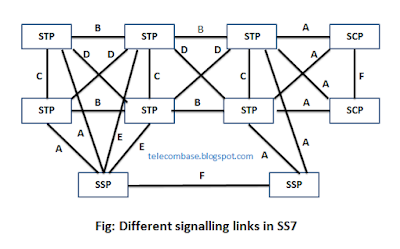
SS7 is a network of its own.
This network consists of 3 major parts:
STP, SCP and SSP
A)
Signal transfer point(STP):
a)
It is a packed based switch.
b)
It receives and send message signal to proper
destination.
c)
It also forms specialized routine function.
B)
Service control point (SCP):
a)
This node acts as a database which provides the
information for the advanced call in the network.
C)
Service signaling point(SSP):
a)
This node is the end exchange equipped with SS7
enabled software and having signal lines.
b)
Every
will have SSP to connect with SS7 network.
c)
SSP’s behaves like an exchange for different
functions like starting the transmission as well as termination of the line in
the network.
d)
SSP’s are connected with other STP’s and SCP‘s
in the ss7 network.
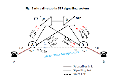
There are different steps in SS7 call setup:
1.
Switch A analysis the dialed digits and
determines that if it needs to send the call to witch B.
2.
Switch A selects a idle trunk between itself and
switch B, and formulates IA M(Initial Address message), the basic
message needed to initiate a call. The IAM addressed to switch B. It
identifies the initiating switch (A) , the destination switch (B), the trunk
selected, call and calling numbers and other information.
3.
Switch A picks up one of it’s a link (Aw)
and transmits the message IAM over the selected link to routed to switch(B).
4.
STP -W receives the message, inspects its routing label and determines if it is to
be routed to switch B. it transmits the message to switch over a link(BW).
5.
Switch B
receives the message. On analyzing the message, it determines if servers the
called number and the called number is idle.
6.
Switch B formulates an ACM(Address complete
message) which indicates that the IAM has received its destination.
The message identifies the receipt switch (A), sending Switch(B) and the
selected trunk.
7.
Switch B picks on link B-X and transmits ACM
over that link for routing to switch A. At the same time, it completes the call
path in the backward direction (towards switch A), sending a ringing tone over
the trunk towards switch A and rings the line of called subscribers.
8.
STP-X receives the message, inspect its routing
label and determines that is is to be routed to A. it transmits the messages to
A.
9.
On receiving ACM, switch A connects the called subscriber to the
selected trunk in backward direction (to switch B) so that the caller can
hear the ringing tone sent by switch B.
10.
When the called subscriber picks up the phone,
the switch B formulates an ANM (Answer Message) identifying the intended
receipt switch(A), the sending switch(B) and the selected trunk.
11.
Switch B select the same link BX to transmit AM
and transmits it to STP X. by this time, the trunk also must be connected to
the called link in both directions to allow conversation.
12.
STP X recognizes that the ANM is addressed to
switch A and forwards it over the same link AX.
13.
Switch A ensures that the calling subscriber is
connected to the outgoing trunk and that the conversation can take place/
14.
If the
calling subscriber hang-ups first, switch A will generate a message REL (Release
message) addressed to B, identifying the
trunk associated with the call. It sends REL to STP-W over the link Aw.
15.
STP W receives REL message determines that it is
addressed to switch B and forwards to switch B over BW link.
16.
Switch B receives the REL, disconnects the trunk
from the subscriber link, returns the trunk to idle status, generates a release
complete message(RLC) addressed back to switch A and transmit it to STP X over
link BX.
17.
STP X receives RLC, determines that is addressed
to A and forwards to switch A.
18.
On receiving RLC, switch A idles the identified
trunk.


2 comments:
Nice Article, thanks for this information
Also check this out
Laptops, Mobiles, Games, Tv, Smartwatches etc Daily Tech News Updates.
Nice info. keep posting.
Voip Cloud Phones System
Cloud business phones
Post a Comment